

Command of the Week - Curves (Week 27)
 Monsen
Administrator 🖼️ 82 images Cartographer
Monsen
Administrator 🖼️ 82 images Cartographer
Index
- List (Basic)
- Symbols Along (Intermediate)
- Fractalise (Intermediate)
- Edit Text (Basic)
- Link with Map/File (Intermediate)
- Offset (Intermediate)
- Measuring Tools (Basic)
- Change like draw tool (Basic)
- Modifiers (Intermediate)
- File Paths (Intermediate)
- Complex Shapes [Combine Path] (Intermediate)
- Complex Shapes [Multipoly] (Intermediate)
- Break (Intermediate)
- Map Notes (Basic)
- Coordinates (Intermediate)
- Macros (Advanced)
- Search Files for Text (Basic)
- Text Justification (Basic)
- Mirrored Polygons (Intermediate)
- Managing Drawing Tools (Intermediate)
- Named Views (Basic)
- Symbol Lookup Sheets (Intermediate)
- Symbol Catalog Settings (Advanced)
- Symbol Catalog Filters (Advanced)
- Symbol Control Points (Advanced)
- Define Symbol (Intermediate)
- Curves (Basic)
- Selections (Intermediate)
- Sort Symbols in Map (Basic)
- Extract Properties (Basic)
- Convert File (Basic)
- Get Extents (Advanced)
- Quick Move (Basic)
- Menu Editing (Advanced)
- Trace (Basic)
- Array Copy (Intermediate)
- Explode (Basic)
- Clipboard Copy (Basic)
- Rename & Reorder (Intermediate)
- Drawtools Edit (Basic)
- Trims (Basic)
- Symbol Attributes (Intermediate)
- Fill Style Selection Mask (Basic)
- Browse Files (Basic)
- Node Editing (Intermediate)
- Automatic Sheet Selection (Basic)
- Scale (Basic)
- Text along a Curve (Basic)
- Shaded Polygons (Intermediate)
- Fill with Symbols (Intermediate)
- Global Sun (Basic)
- Symbols in Area (Intermediate)
This series is called the command of the week, but it could also explain a feature. The explanations will tend to explain the technical parts of the command, and is intended to highlight the basics (and complexities) of the command, and information about how to use it, but won't be a detailed tutorial. It is up to you to use it creatively in your maps.
Week 27 - Curves
Most people will be familiar with the smooth path (and smooth polygon) which is probably the most used curve in CC3+. But there are other options.One of the great things about curves in CC3+ is that they are based on mathematical formulas. The advantage of this is that they retain their smooth shape no matter how much you zoom in on them, they will never break down into straight segments, nor will they be pixelated*.
* Note that because a computer display is built up from a grid of pixels, everything which is not strictly horizontal or vertical will appear pixelated when rendered on screen. Anti-aliasing can help mitigate this, but CC3+ doesn't apply anti-aliasing to the image rendered on screen. Do note that since this pixelation is a limitation of your screen and not the actual line, it will ot increase as you zoom in to the line, as opposed to a line in a raster editor, where the pixels would be more and more pronounced as you zoom in. You can apply a weak blur to the line, this will have the same effect as anti-aliasing. In this case, I recommend using a blur size expressed in percentage of view width, thereby having the same size of the blur no matter your zoom level. Also note that when you render the CC3+ map out to an image, that image will be a regular raster image, without any of the nice features the curve has in CC3+, like unlimited pixel-free zooming
Where to find them?
Toolbar: (right click) [Image_9010], (right click) [Image_9011], (right click) [Image_9012], (right click) [Image_9013]Menu: Draw -> Path, Draw -> Arc, Draw Polygon, Draw -> Circle
Command Line: PATHD, ARCD, POLYD, SPLINE, SPLINE2, PSPLINE, BEZ, ARCB, ARC3, ARCS, ARCR, CARCD, ARCW, ELIPA, CIRP, CIRR, CIRD, CIR2, CIR3, DONUT, ELIPP
How to use them
The interesting parts of a curve is how it is drawn on screen depending on the nodes you place. Beginners may get a bit frustrated, because it seems like the smooth polygon never covers the area you specify. Truth be told, smooth entities can be a bit tricky, but knowing how they work certainly help. Let us discuss the various basic options we have.Curve aids
The best aid to use when working with curves is frames (Tools -> Drawing Aids -> Toggle Frames). Frames shows a thin line between the nodes, which helps to pinpoint the exact positions of these. Frames typically manifests like a straight "border" around our smooth entity. For all my screenshots below, I have turned frames on.Paths vs Polygons
A polygon is basically just a closed path. The behavior when it comes to smoothing is basically the same, so I'll be talking most about paths here, as to avoid repeating myself. The main difference is that a polygon doesn't have any special start/end points, all nodes are treated as middle nodes.[Image_9014]
Cubic curve
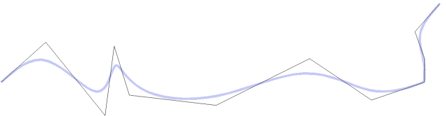
When you use the default smooth path or smooth polygons in CC3+, you are using a cubic curve. This is characterized by touching the start and end point, but for all other points, the position of the line is averaged between the points. What this means in practice is that when you place a point, the shape of that segment of the path isn't determined until you place the next point, because it needs to average the position between these. Note that with a cubic curve, the line itself will never touch any nodes except the first and last node. You can however make a sharp corner in a specific place by placing two nodes on top of each other in that point. You can see that point in my example to the left at the sharp turn where the frame actually meets the bend of the line.You can check if a line uses cubic curves by using list on it and check if it's smoothing method property is Cubic B-Spline
[Image_9015]
Parabolic Curve
A path using parabolic smoothing will touch all the nodes. The path itself is drawn the same way as a cubic curve, but the result typically results in sharper angles. Just as with the cubic smoothing, the exact shape of a segment is only determined when you place the next node in the chain, since the smoothing computation depends on it. It is also worth nothing that you cannot use double node trick to get sharp corners with parabolic smoothing, as can clearly be seen in the example image to the left. However, this is less needed with parabolic curves anyway, since the curve touches the nodes anyway.You can check if a line uses parabolic smoothing if the smoothing method property is Parabolic Spline.
[Image_9016]
Bezier Curve
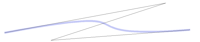
A bezier curve in CC3+ consists of four nodes. The first two placed are the start and end nodes, while the third and fourth modifies the shape of the curve. Node that it can never have more than these four points, so a bezier curve cannot be used for a longer path, nor can it be closed to make a polygon. Forthe mathematics behind a bezier curve, check out this wikipedia article.You can check if a line uses bezier smoothing if the smoothing method property is Cubic Bezier.
[Image_9018]
Arcs
An arc is defined as a segment of the circumference of a circle. As such, an arc will always have the shape of a partial circle. However, the curvature is determined by the radius of the circle, so while the shape is fixed, adjusting the radius of the circle and the length of the segment provides a lot of flexibility in the appearance. The example image to the left shows different variations of arcs. Note that an arc is not a path. If you ever need to treat it like a path, you can convert it by using Line to Path [LTP2] on it. This will convert it to a regular path. You can then proceed to make it smooth by using Straight to Smooth [STC] on it, and it should appear very similar to the original arc entity.


Comments
(The closest I can come to doing this is to place a second point near the end point.)
Also of interest, how does the spline behave when trimmed? Does trim calculate a new end point and then the spline is recalculated based onthe points or is the path/trace of the spline remain the same (by keeping the values of the truncated point(s) for calculations and just stopping the display part of the curve at the appropriate point)?
The entity keeps all it's nodes, it just stops displaying at the point you trimmed it. Note that CC3+ still sees this as a valid endpoint, for example to use with the endpoint modifier.
If you use LIST on it, you can see two parameters, start parameter and end parameter. This basically tells which range of nodes to include in the display (decimal values are relative distance along the line between the nodes)