

Watabou City REVISED (annual 157)
 Quenten
🖼️ 125 images Mapmaker
Quenten
🖼️ 125 images Mapmaker
Since this great annual came out, Watabou had done heaps of modifications. And as a result, the SVG to DXF conversion doesn't work as seamlessly as before, making everything lines, and therefore unable to use the method as outlined in the annual.
I have experimented with this, and come up with the following solution, which makes everything relatively easy again.
Please try it out, and let me know if there are any bugs. Perhaps we can convince Ralf to do a revision of this.
I have also added a few of my own idiosyncrasies in the sheet naming.
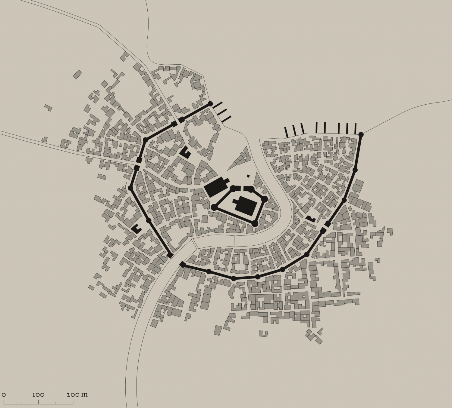
This is the png of the city I generated.
I also attach the SVG for any interested.
The first most important thing is to just export as a SVG the actual elements you want and cut out all the pretty stuff. It is, after all, the street and building layout that we really want.
So ... in the generator, first check colour - make this either B&W, or Ink in the Presets.
Next, click on Style, and make sure you check or uncheck the following. Whatever I don't mention, you can choose as you wish.
- GRAPHICS: Check thin lines, leave the rest unchecked.
- ELEMENTS: Districts Hidden. Check scalebar only (if you want it, leave the rest unchecked
- BUILDINGS: Roofs plain, leave Raised unchecked. Otherwise, choose what you want.
- OUTLINE: Check buildings, water and roads
- MISC: Check Solids; Uncheck Show alleys and Show trees. I advise against choosing farms - they can be added as you wish, and I use the farms from other styles, especially where I can easily align the furrows using Shaded Polygons.
You should get something like the png above. ie B&W, no text or trees or extraneous lines.
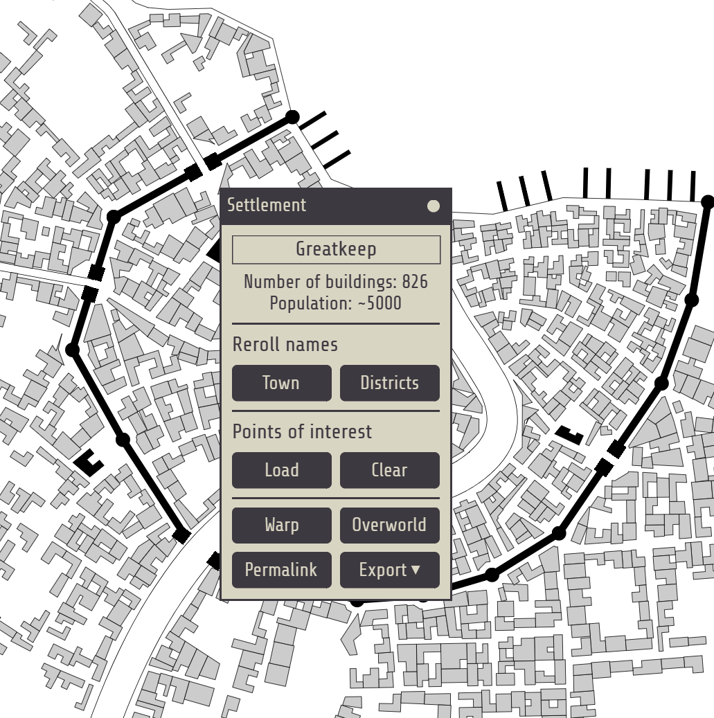
The number of Buildings and suggested population is available on the Settlement menu:


Comments
The next step is to export as png, and SVG. Then convert SVG to DXF using the tool mentioned in the annual. i have tried other tools, and they leave even more of a problem. However, if any of our gurus know of a better converter, that may do the same as originally in the annual, and not make everything lines, then that would be great. Just a shout out to @Ralf , and @Monsen
Then open Watabou city annual style. Pick the dimensions you want - get this from the scale in the generator.
Then inset the dxf file.Scale it as non visual by factor of 2.5 (not 400 - it no longer appears as a dot!). Use 0,0 as the point to scale from.
Next step - convert all from lines to paths (right click the Explode button). DO NOT FORGET THIS
Now we need to move all elements apart from the buildings to their relevant sheets and layers. I do it in this order, but it doesn't really matter which so long as you remove all elements apart from the buildings to their relevant sheets/layers.
Now I have got the following - easy to add all the other bits to the map now.
To the template for this revised annual, I would add the following sheets: PARKS, BRIDGE, BRIDGE TOP, DOCKS, BUILDINGS HIGH; and the following Layer: Cartouches. I would also change the sheet effects for the CITY BLOCK and CITY BLOCK OUTLINES as indicated above (and change the names to BUILDINGS AND BUILDINGS OUTLINE)
I will finish this map off later.
I really want comments and suggestions on this please. I would love to be able for us all to use the Watabou stuff easily again.
Here is what it looks like with all the bells and whistles from the Watabou generator now. You can even add you own text for various buildings of importance.
Great work! This should be made into a new annual or at least worked into the original and re-released.
I'm hoping people will try it out, and let me know of any bugs, or suggestions, so I can then talk to @Ralf about a revision of the annual. And I am sure he will also have even better ideas than me.
Did the Random Dungeon Generator in last year's Humble Bundle have an SVGREAD command?
I don't know.
Here is an illustration of one problem I am having with the Change like Draw Tools command on various aspects of the dxf.
You can see the ones that worked well - the parks, the body of water (lake,sea), the city blocks (see comment below), the city walls.
But for the roads and river, they produced the hollow version, which cannot be changed to solid. Interestingingly, the roads within the city walls came out well, but not beyond that. The river just didn't work at all. I don't know why this is the case. After converting everything from Line to Path, the river and road were each a single path (2D Polygon) of 0 width.
Here is the fcw post using the Change like Draw tool, and also the one with the DXF, one just as it is, the other with everything converted using Lines to Paths. It would be great if someones could shed light. Otherwise, the rivers and road will have to be redrawn separately - which is not really much of a problem.
FCW for this jpg.
FCW with just DXF added with no modifications:
FCW with DXF changed with Lines to Path tool.
Also a jpg showing the culprits in red.
And here is the final version of the map - I will see if I can find a place in the Atlas for it.
The problem lies here:
After converting everything from Line to Path, the river and road were each a single path (2D Polygon) of 0 width.
A 2D polygon isn't a path, it is a polygon. When applying the river draw tool, which is a line-type tool to a polygon, you get weird effects. When a line has a line width, it is shown as a solid entity of that width, but when a polygon gets a line width, it is shown as a hollow entity with an outline of that width.
So why was in converted to a Polygon instead of a Path? This is down to the fact that the river isn't made up from just one series of lines, but they are actually doubled up. This causes CC3+ to see interpret this as a set of lines that goes all the way to the end and back to start again, so since it ends where it started it is interpreted as being a polygon. This means you get a very thin polygon, but a polygon still.
You can easily get this into the desired path by using the Break command on it. Just place the start of the break at one end of the new "polygon" and the end of the break at the other end. This will basically remove one half of the poly, and leaving behind the line representing the other half as a proper 2D Path.
Thanks so much, Remy. I would never have figured that out for myself. I guess the same will be for the roads.
I decided to really test the system and do a large city using the method above. This took just over 60 minutes, but not so bad really for this size city. FCW included if anyone wants to use it. I haven't added anything extra to what the actual city generated, ie no trees, hills, forests, swamps, invading troops, cluster bombs etc - the sort of normal stuff any city has these days.
Larger version in gallery.
I didn't bother to use Shaded polygon by Edge on the fields - i would do so if I was going to develop this city further. Does anyone want me to - perhaps an Atlas add?
Thanks for this Quenten.
This will prove useful to many of us I think.
This took less than 10 minutes to go from starting to insert the DXF to this. I have solved the problem of the road and river - it lies in the original setup of the map to export as SVG - make sure river and roads are NOT outlined. Even if they seem to disappear, they will be present on your svg, therefore DXF.
Once I am completely satisfied with the whole process, i will upload the whole process along with a new Template and DrawTools for both metric and (ugh) imperial. And the fills I use for the fields.
I will be renaming the CITY BLOCK sheet to SYMBOLS BUILDINGS.
"....I have solved the problem of the road and river - it lies in the original setup of the map to export as SVG - make sure river and roads are NOT outlined. Even if they seem to disappear, they will be present on your svg, therefore DXF."
So, THAT'S what was going on! It was driving me insane! Thanks indeed, Mr. Quenten
Cal
I've done something to my settings on the Watabou generator and can't figure out what it is. My generated towns are not displaying well; they're cutting off edges, parts of labels are disappearing, etc. The menu button disappears as soon as I move the mouse. I can't see a way to reach out to Watabou directly, so I'm wondering if someone here with stronger kung-fu than I can help. Screenshot below as an example.
Is that what you get when you export to png, from the generator?
Medieval Fantasy City Generator by watabou (itch.io)
Sadly, no - that's a screenshot from the generator site itself.
Mmmm. My screenshots are all normal. Just did one now.
here is one with text.
So I don't know why your export isn't working. It may not be due to the generator.
@Quenten I'm having the same issues with the Watabou generator Maidhc is having. I just generated three incomplete maps in a row. They are all missing various pieces and the names are all cut off. Even the on screen menu doesn't show up properly.
Perhaps there are some settings which need to be adjusted to make the maps display correctly, but I haven't got a clue what those might be.
Mmmmm. I don't know what is happening. I don't get the same problem. Can you check that you are using the same URL as me? And on the generator, there is a conversation thread (Community) below what you generate - perhaps you could ask watabou there what the problem is. Also, make sure you click on the Follow Watabou, in the submenu on the right hand top corner.
Here is the final draft of the revised way to use the Watabou city annual to convert watabou cities into CC3+
I will post my revision of the Templates and Drawing tools later on. Unless @Ralf thinks that would violate the ProFantasy agreement. They will be titled Annual Watabou City QW, to distinguish them from the official version, and they will also have their own Drawing Tools and bitmaps - again, drawn from existing CC3+ bitmaps - hence I will await to hear what Ralf says before posting.
But they will fix the problem with the present annual, given all the developments in the watabou city generator since that annual came out.
With reference to the rendering issues...
Compare your browsers and windows versions as well.
I'm convinced it's something in my Windows settings for that site. It was working fine until a few days ago, but it changed mid-map while I was making some tweaks to the displays. I was hoping that either someone here had experienced the same issues and figured out how to resolve them, or had a way to contact Watabou directly. Since that doesn't seem to be the case, I'll reach out to them on the community link on the site.
Thanks anyway, Quentin et.al., for trying! I appreciate the effort!
OK, watabou referenced a reddit post where the user fixed the issue for a short time by opening the site in Edge rather than Chrome. I tried that, and it worked but the issue then reappeared in Edge as well. That led me to what I believe is the real solution.
@Elfling I use the browser settings to set my zoom on most websites to 75% or so. This causes no issues with the watabou sites initially, but when I close the tab and then return to the site later (with the zoom already set to 75%), that's when the issue occurs. Resetting the zoom to 100%, leaving the site/closing the tab, then returning to the site fixes the issue for me, at least.
Here are some of the Drawing tools I am working on for a new version of Watabou Cities.
Please comment.
And if any of you have better ways to do crenalations with a drawing tool or macro, please let me know.
re Crenlations
https://forum.profantasy.com/discussion/8114/castle-wall-tower-crenelations
Ralf did a Live video where he designed crenellations using a line style. (Has some odd effects when drawing circular crenellations on a round tower, though.)
https://www.youtube.com/watch?v=XnjFECIl7ZU
I have used the line style made by Ralf in that video, and am happier with the towers and walls now. Though because the walls are still a line, the crens are still not totally perfect. Not sure how I can turn a 10' wide line into a 10' wide polygon, using a drawing tool.
Not sure why the round tower on the gatehouse at the top didn't show the same as the round tower below - it did in the FCW, but somehow, not in the jpg.