

Line Oddities when exporting as PNG
 thehawk
Surveyor
thehawk
Surveyor
Galik inspired me to revisit my own oldgames maps for a while. I am currently attempting to do an approximation of an estimation of an emulation of the original Eye of the Beholder City of Waterdeep Sewers map that comes with Eye of the Beholder for those maps.
To do that, I drew it out on the Walls sheet as normal. Then created a new Walls 2 sheet 'above' the Walls sheet. I drew over the outline with a color that matched the parchment background.
When I look at the results in CC3, it looks good. However, when I save as a PNG, I get odd lines that don't show up while in CC3. The lines that show up are different depending on whether I do a rectangular section (which is what I normally do) or just PNG bitmap file. They do seem to be consistent with the export type though.
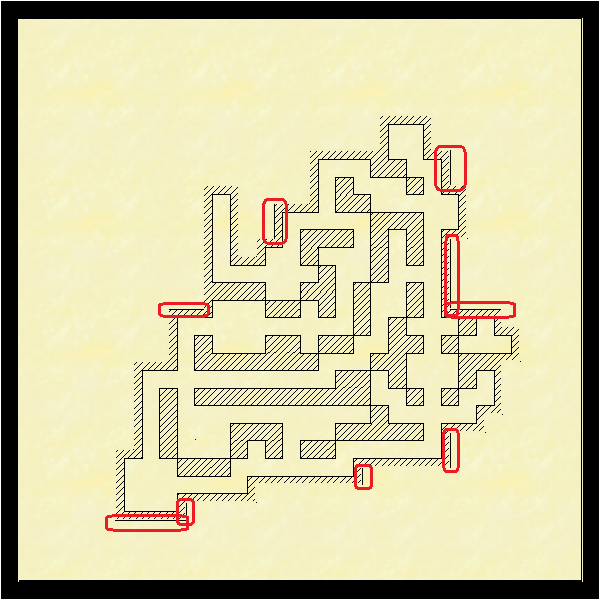
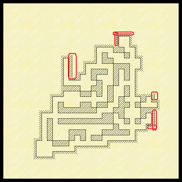
In the below, the first one with the white border is the PNG bitmap file export. The next one is the rectangular section PNG.
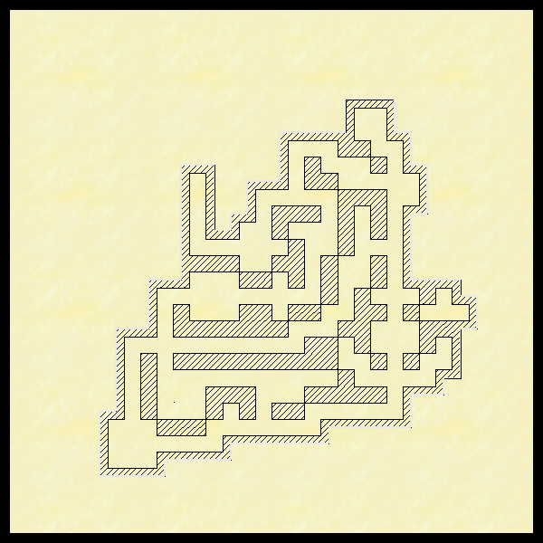
I had to do a custom palette to get the right color to match the parchment background. Wondering if that was causing the problems, I reverted to the default and tried again. The third item is the result of that.
To do that, I drew it out on the Walls sheet as normal. Then created a new Walls 2 sheet 'above' the Walls sheet. I drew over the outline with a color that matched the parchment background.
When I look at the results in CC3, it looks good. However, when I save as a PNG, I get odd lines that don't show up while in CC3. The lines that show up are different depending on whether I do a rectangular section (which is what I normally do) or just PNG bitmap file. They do seem to be consistent with the export type though.
In the below, the first one with the white border is the PNG bitmap file export. The next one is the rectangular section PNG.
I had to do a custom palette to get the right color to match the parchment background. Wondering if that was causing the problems, I reverted to the default and tried again. The third item is the result of that.
Comments
Its hard to say for sure without the FCW to examine, but it may be that you matched the colour so very well that you have some transparency acne going on there with bits of them not registering as separate from the background. Changing patterns with different zooms is one of the telltale symptoms.
Try hiding the outer lines using a Color Key sheet effect rather than placing background coloured objects on top of them.
If you would be willing to upload the FCW we would soon be able to see if TA was the cause or not.
The only sheet effects I know about are TC, not TA. So will have to look into how to do that.
The exact issue here is basically one of calculation when things get small. At the scale those maps above are exported, there isn't enough pixels in your map to make those "cover walls" in your map a full pixel wide. Unfortunately, pixels cannot be partial things, they either contain one color or another, they cannot be split, as they are the smallest unit in an image. So, when that happens, the rasterization process needs to decide, that line is less than a pixel, should I round it up to 1 or down to 0? One might thing rounding it up to 1 is the good thing since you do want them visible, but for every time you do that, you steal pixels from something else in the map. So when something is less than a pixel, it will sometimes be 1 pixel, sometimes 0. So in short, some of those cover walls just disappears because there isn't room to show them.
But where really makes your problem here is that outline of the shaded area of yours is outlined in a 0-width line. Those lines are special in that they are always drawn as thin as possible, but they are always visible. So they are always one pixel no matter the zoom level. So when that wall hiding line disappears because it is too small... Well, that outline below it won't, because it is always that small.
So, how to deal with this?
One way is to simply export the image much larger and then reduce it afterwards. As long as the covering lines had enough space on the export to appear all of them, they won't magically disappear when you resize the image afterwards, it is just a case of making sure they are given room during rendering. This can be done by exporting a higher version and resizing in an image editor, or you should be able to do the same by setting the expected size in CC3+ and use a really high anti-aliasing value (probably need 100% if you really want your results as small as in this post) as this will export a much larger image and then scale it down to compute AA.
You can also try covering them up with other 0-width lines instead of wider lines. I am fairly certain that would work fine. As long as things are placed using snaps, you can easily place another 0-width line exactly on top of it. And that zero-width line should have the same behaviour as the line below and allways show, and allways be exactly large enough.
I did try the color key sheet effects, but couldn't get it to work. Either because I was trying to oversimplify, or because that outer wall is really a multipoly, so all the same color and all the same sheet - and in hiding part I was hiding all. I decided to stick to thread count for sheet effects.
Based on your data, I pulled things apart to not do this overlapping entities to hide things. I changed the fill style to not have an outline. After I drew my inner track of what would become the multipoly as a solid LS / solid FS. I copied it to its own sheet above the walls sheet and hid it out of the way. Then drew the outer track of the multipoly with a solid LS / solid FS, and multipolied the two together using the new FS. It now shows up as just the diagonals with no outline. Then unhid the previously hidden inner track copy sheet. So far, everything looks like it works the way I want it to.
Then I threw all the previous work out, put everything you two have taught me into a new template, and that's as far as I have gotten.
Thank you!