

Monsen
Monsen
About
- Username
- Monsen
- Joined
- Visits
- 660
- Last Active
- Roles
- Administrator
- Points
- 8,858
- Birthday
- May 14, 1976
- Location
- Bergen, Norway
- Website
- https://atlas.monsen.cc
- Real Name
- Remy Monsen
- Rank
- Cartographer
- Badges
- 27
Latest Images
-
How to export very large maps
The ".png.bmp" filename is part of the process. If you see a file with this ending, it basically just means the export crashed halfway through.
Basically, what happens is that CC3+ needs to render the entire map before it can be converted to png, it cannot simply be exported straight to png or jpg, and the native format of windows is BMP. So what it does is that it always exports the file to .bmp first (this is the map.png.bmp file), and then at the end converts it to png (or jpeg) which results in a new file, map.png, and then the original bitmap file (map.png.bmp) is deleted. But if this file is still around, it usually means CC3+ crashed during the export so it never got to the conversion and deletion steps.
Do the crash only happens when you go up to 9000x9000? I see you mention 6000x6000 being to small, so I assume that one actually exported?


-
SOLVED: Why are my Dungeons of Schley textures blank in DD3?
By default, templates only contain references to the fills used for the style (You REALLY don't want to have them all listed, trust me :)), so that means that drawing tools not made for the current map style will show up using the currently selected fill (see your status bar), instead of the actual fill used by that tool in it's native environment. (Your current map seems to be the Ancient Tombs style)
There's more information in this FAQ topic, including how to import the fills to the current template:

-
stone carvings
Check out this article:

-
Is there an easy way to tell which light is which?
Use the :CC2EDIT: command on the lights directly in the map (visualized by a cross in the light's color)

-
keyboard shortcuts or commands
Almost everything in CC3+ can be done using a command instead of using the mouse. If you have the Tome, there are full command lists at the end of each chapter (the one at the end of the CC3+ section is the largest), and it also came with an excel file that is found in @documentation\tome\ that lists all the commands.
Common commands also have shortcut keys. You can easily see this just by clicking a bit around in the various menus at the top of CC3+ (Or to avoid clicking, hit and release the Alt key, and the menu should be activated and can be navigated with arrow keys.)
You can even edit the CC3+ menu files and add your own shortcuts if needed.


-
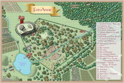
August Mapping Competition - The Results
And here's Sue's Town Hall:

-
Snowy lands
This will happen if the fill isn't defined in the map, such as if you are using an existing map made before this fill was added, in which case you must import the fill into the map first. See this FAQ entry:


-
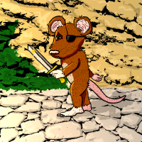
Panzer sample thread
You know what, one of the original suggestions on the back of the CC3 DVD case was "A historical battlefield littered with burnt-out tanks". While a great image, this has never been possible with CC3(+) unless you found and imported images yourself or happened to be incredibly much better at drawing than me.
So, now you have a change to correct this (We obviously need both burnt-out and non-burned-out tanks). This should be an annual.


-
Merging polys -- how?
If they are partially overlapping, the simplest way to merge them is with the TRACED command. This will create a new poly, so delete the other two afterwards, and change properties on the new one if required.
The link below shows how to use TRACED. The example uses a single bitmap image, but it works just as well on a set of polys.

-
CC3+ Connecting nodes (to connect passages)
This is one of the situations where it isn't that difficult to do, but the explanation may look a bit involved at first. This is a bit extra complicated because I see you are using a custom version of the drawing tool, but you haven't set the sheet and layer settings for the outline properly.
Connecting it will require a bit of manual work since you cannot use the edit feature of the drawing tool, since that will just extend it from one side, but not connect the other. There is also the complication that regular polygons cannot have holes in them, but connecting it up will end you up with a hole in your floor poly immediately to the left of where you are connecting up. There are a couple of ways to do this, but some node editing and a multipoly is probably the way to end up at the desired result here. Keep in mind that a multipoly isn't editable with the drawing tools edit features, so this should be done when you are done drawing the system.
First, keep in mind that the wall line is a separate entity. We'll start by editing this one. To avoid editing the floors instead (easy to do when two entities overlap), start by hiding the BACKGROUND (FLOOR 1) layer, this should leave you with just the wall entity.
Use change properties to move your wall entities to the WALLS sheet and the WALLS layer. If you find yourself unable to select it at this point, it is because it is on the HEX/SQUARE GRID layer, and that layer may be frozen. If so, you must first enter the layers dialog and unfreeze that layer.
Then use :CC2BREAK: on the wall to create a gap in both the upper and lower section where approximately where you want the joining segment to meet up. (When selecting an entity to break, the point you used to first select it on defines the part of the entity to keep)
Now, right click :CC2EXPLODE: and pick Path to Poly. You're going to use this twice, first on the small wall that goes around that little "hole" to the left of your marked area, then on the main wall going around the rest. This should leave you with two walls, one outer and one inner. If you are unhappy with the straight connecting lines, you can add some detail by using :CC2INSNODE: to add a few more nodes in the walls.
Now, show the floors again by unhiding BACKGROUND (FLOORS 1). The existing floors are of no use to us, so we are going to erase them but let us just pick up their settings first, so use :CC2KEEP: on it first, then :CC2ERASE: it.
Now, right click :CC2COPY: and pick Copy to Sheet. Use this to copy both your wall lines to the FLOORS sheet.
Hide the walls sheet. The walls you see now are the copies on the FLOORS sheet. Use :CC2MCHANGE: on the large outer one, and just hit OK. The default values in change properties is the current properties, which we got from the old floors when we used extract properties on it earlier. The large polygon should now look like your floors
Finally, to make the hole, use :CC2MPOLY2: to combine the floor poly with the smaller wall segment. The wall segment may be hidden below the floor poly at this point, but you know where it is, and should be able to pick it up using a selection rectangle even if you cannot see it. You'll see that you have succeeded when the selection counter tells you that you have two entities selected. Be vary of the grid, you don't want to select that.
Now all that remains is to show the WALLS sheet again, and you should have both your floor and the walls.